
|
Octave-Forge - Extra packages for GNU Octave |
| Home · Packages · Developers · Documentation · FAQ · Bugs · Mailing Lists · Links · Code |
|
|
Octave-Forge - Extra packages for GNU Octave |
| Home · Packages · Developers · Documentation · FAQ · Bugs · Mailing Lists · Links · Code |
Function File: [omesh,nodelist,elementlist] = msh2m_submesh(imesh,intrfc,sdl)
Extract the subdomain(s) in sdl from imesh.
The row vector intrfc contains the internal interface sides to be maintained (field
mesh.e(5,:)). It can be empty.Return the vectors nodelist and elementlist containing respectively the list of nodes and elements of the original mesh that are part of the selected subdomain(s).
See also: msh2m_join_structured_mesh, msh3m_submesh, msh3e_surface_mesh.
The following code
name = [tmpnam ".geo"];
fid = fopen (name, "w");
fputs (fid, "Point(1) = {0, 0, 0, .1};\n");
fputs (fid, "Point(2) = {1, 0, 0, .1};\n");
fputs (fid, "Point(3) = {1, 0.5, 0, .1};\n");
fputs (fid, "Point(4) = {1, 1, 0, .1};\n");
fputs (fid, "Point(5) = {0, 1, 0, .1};\n");
fputs (fid, "Point(6) = {0, 0.5, 0, .1};\n");
fputs (fid, "Line(1) = {1, 2};\n");
fputs (fid, "Line(2) = {2, 3};\n");
fputs (fid, "Line(3) = {3, 4};\n");
fputs (fid, "Line(4) = {4, 5};\n");
fputs (fid, "Line(5) = {5, 6};\n");
fputs (fid, "Line(6) = {6, 1};\n");
fputs (fid, "Point(7) = {0.2, 0.6, 0};\n");
fputs (fid, "Point(8) = {0.5, 0.4, 0};\n");
fputs (fid, "Point(9) = {0.7, 0.6, 0};\n");
fputs (fid, "BSpline(7) = {6, 7, 8, 9, 3};\n");
fputs (fid, "Line Loop(8) = {6, 1, 2, -7};\n");
fputs (fid, "Plane Surface(9) = {8};\n");
fputs (fid, "Line Loop(10) = {7, 3, 4, 5};\n");
fputs (fid, "Plane Surface(11) = {10};\n");
fclose (fid);
mesh = msh2m_gmsh (canonicalize_file_name (name)(1:end-4), "clscale", ".5");
mesh1 = msh2m_submesh (mesh, 7, 9);
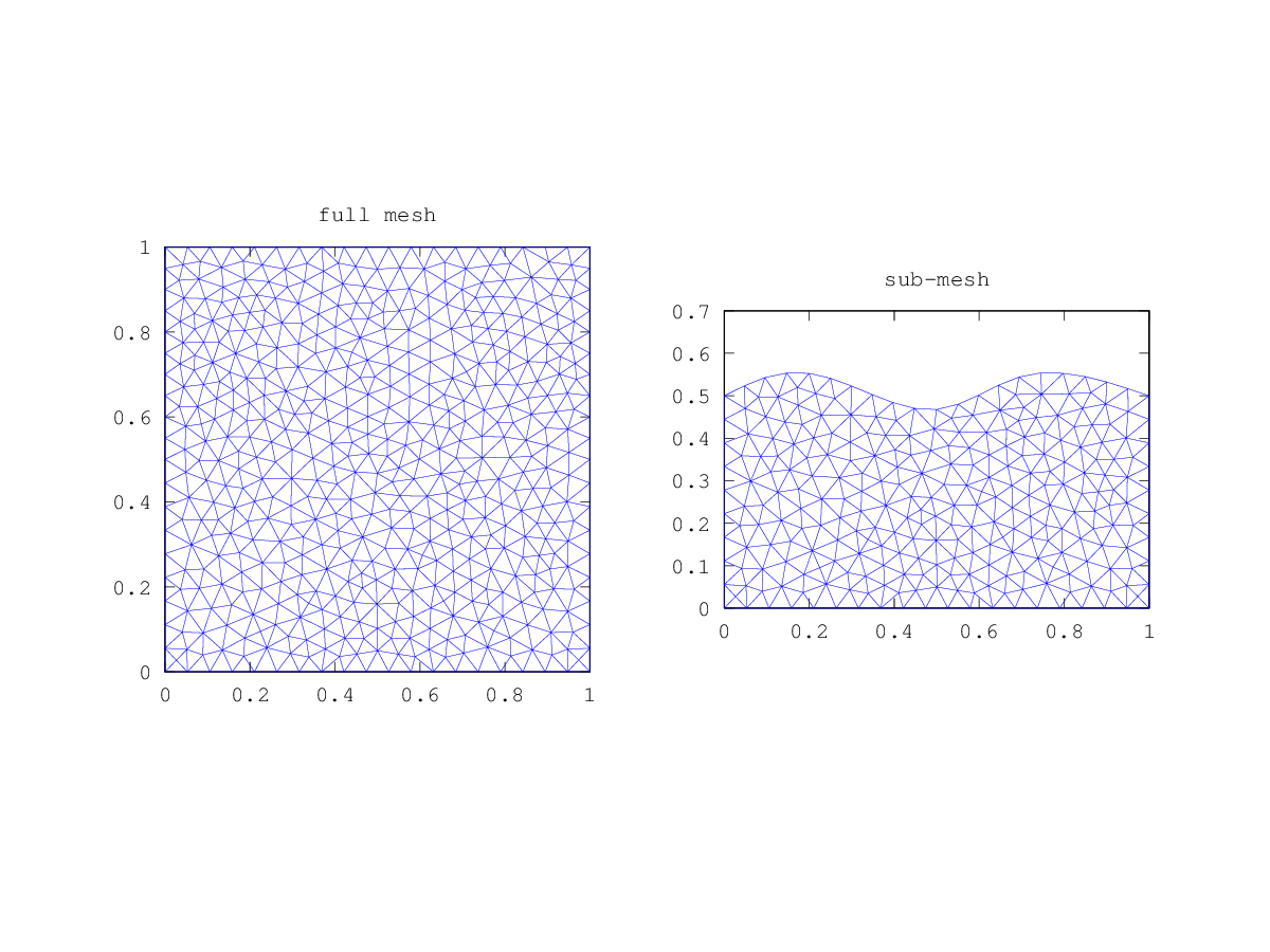
subplot (1, 2, 1);
trimesh (mesh.t(1:3,:)', mesh.p(1,:)', mesh.p(2,:)');
axis ("equal"); title ("full mesh")
subplot (1, 2, 2);
trimesh (mesh1.t(1:3,:)', mesh1.p(1,:)', mesh1.p(2,:)');
axis ("equal"); title ("sub-mesh")
unlink (canonicalize_file_name (name))
Produces the following output
Generating mesh...
Processing gmsh data...
Creating PDE-tool like mesh...
Check for hanging nodes...
Setting region number in edge structure...
Deleting temporary files...
ans = 0
and the following figure
| Figure 1 |
|---|
 |
Package: msh