
|
Octave-Forge - Extra packages for GNU Octave |
| Home · Packages · Developers · Documentation · FAQ · Bugs · Mailing Lists · Links · Code |
|
|
Octave-Forge - Extra packages for GNU Octave |
| Home · Packages · Developers · Documentation · FAQ · Bugs · Mailing Lists · Links · Code |
Circuit file parser that can interpret a subset of the spice file format.
prs_spice currently supports the following set of "Element Cards"
Cname n+ n- cvalue
Cname anode knode modelname <parameters>
Mname gnode dnode snode bnode modelname <parameters>
N.B.: one instance of a MOS element MUST be preceeded (everywhere in the file) by the declaration of the related model. For instance:
.MODEL mynmos NMOS( k=1e-4 Vth=0.1 rd=1e6)
M2 Vgate 0 Vdrain 0 mynmos
Rname n+ n- rvalue
Vname n+ n- <dcvalue> <transvalue>
Transvalue specifies a transient voltage source
SIN(VO VA FREQ TD THETA)
where:
Currently the damping factor has no effect.
Pulse
PULSE(V1 V2 TD TR TF PW PER)
parameters meaning
Currently rise and fall time are not implemented yet.
.MODEL MNAME TYPE(PNAME1=PVAL1 PNAME2=PVAL2 ... )
TYPE can be:
The parameter "LEVEL" is currently assigned to the field "section" in the call of the element functions by the solver. Currently supported values for the parameter LEVEL for NMOS and PMOS are:
(see documentation of function Mdiode).
Currently supported values for the parameter LEVEL for D are:
(see documentation of functions Mnmosfet and Mpmosfet).
See also: prs_iff,Mdiode,Mnmosfet,Mpmosfet.
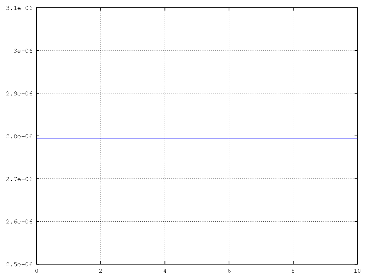
The following code
 outstruct = prs_spice ("rlc");
 vin = linspace (0, 10, 10);
 x = zeros (outstruct.totextvar+outstruct.totintvar, 1);

 for idx = 1:length (vin)
   outstruct.NLC(1).pvmatrix(1) = vin(idx);
   out = nls_stationary (outstruct, x, 1e-15, 100);
   vout(idx) = out(2);
 end

 plot (vin, vout);
 grid on;
Produces the following figure
| Figure 1 |
|---|
 |
The following code
 ## Circuit

 cir = menu ("Chose the circuit to analyze:",
 	       "AND (Simple algebraic MOS-FET model)",
 	       "AND (Simple MOS-FET model with parasitic capacitances)",
 	       "Diode clamper (Simple exponential diode model)",
 	       "CMOS-inverter circuit (Simple algebraic MOS-FET model)",
 	       "n-MOS analog amplifier (Simple algebraic MOS-FET model)",
 	       "Linear RC circuit",
 	       "Diode bridge rectifier",
             "RLC circuit");

 switch cir
   case 1
     outstruct = prs_spice ("and");
     x         = [.5 .5 .33 .66 .5 1 0 0 1 ]';
     t         = linspace (0, .5, 100);
     pltvars   = {"Va", "Vb", "Va_and_b"};
     dmp       = .2;
     tol       = 1e-15;
     maxit     = 100;
   case 2
     outstruct = prs_spice ("and2");
     x         = [.8;.8;0.00232;0.00465;.8;
 		 .8;0.00232;0.00465;0.00000;
 		 0.0;0.0;0.0;0.00232;0.0;
 		 0.0;0.0;0.0;1.0;0.0;-0.0;
 		 0.0;1.0;0.00465;0.0;0.0;
 		 -0.0;1.0;0.00465;0.0;
 		 0.0;0.0;1.0;1.0;0.0;0.0;0.0;
 		 0.0;0.0;0.0];
     t       = linspace (.25e-6, .5e-6, 100);
     dmp     = .1;
     pltvars = {"Va", "Vb", "Va_and_b"};
     tol     = 1e-15;
     maxit   = 100;
   case 3
     outstruct = prs_spice ("diode");
     x   = [0 0 0 0 0]';
     t   = linspace (0, 3e-10, 200);
     dmp = .1;
     pltvars = {"Vin", "Vout", "V2"};
     tol   = 1e-15;
     maxit = 100;
   case 4
     outstruct = prs_spice ("inverter");
     x   = [.5  .5   1   0   0]';
     t   = linspace (0, 1, 100);
     dmp = .1;
     pltvars={"Vgate", "Vdrain"};
     tol   = 1e-15;
     maxit = 100;
   case 5
     outstruct = prs_spice ("nmos");
     x         = [1 .03 1 0 0]';
     t         = linspace (0, 1, 50);
     dmp       = .1;
     pltvars   = {"Vgate", "Vdrain"};
     tol   = 1e-15;
     maxit = 100;
   case 6
     outstruct = prs_spice ("rcs");
     x         = [0 0 0 0]';
     t         = linspace (0, 2e-5, 100);
     dmp       = 1;
     pltvars   = {"Vout"};
     tol   = 1e-15;
     maxit = 100;
   case 7
     outstruct = prs_spice ("rect");
     x         = [0 0 0 0 ]';
     t         = linspace (0, 3e-10, 60);
     dmp       = .1;
     pltvars   = {"Vin", "Voutlow", "Vouthigh"};
     tol   = 1e-15;
     maxit = 100;
   case 8
     outstruct = prs_spice ("rlc")
     #x         = [0 0 0 0 0]';
     #x         = [0 0 0 ]';
     #x         = [0 0 0 0]';
     x         = [0 0 0 0 0 0 ]';
     t         = linspace (0, 2e-5, 200);
     dmp       = 1;
     #pltvars   = {"Vin", "Vout"};
     pltvars   = {"I(C3)"};
     #pltvars   = {"Vout"};
     tol   = 1e-15;
     maxit = 100;
   otherwise
     error ("unknown circuit");
 endswitch

 clc;
 slv = menu("Chose the solver to use:",
 	   "BWEULER", # 1
 	   "DASPK",   # 2
 	   "THETA",   # 3
 	   "ODERS",   # 4
 	   "ODESX",   # 5
 	   "ODE2R",   # 6
 	   "ODE5R"    # 7
 	   );

 out   = zeros (rows (x), columns (t));

 switch slv
   case 1
     out = tst_backward_euler (outstruct, x, t, tol, maxit, pltvars);
     # out = TSTbweuler (outstruct, x, t, tol, maxit, pltvars);
   case 2
     out = tst_daspk (outstruct, x, t, tol, maxit, pltvars);
     # out = TSTdaspk (outstruct, x, t, tol, maxit, pltvars);
   case 3
     out = tst_theta_method (outstruct, x, t, tol, maxit, .5, pltvars, [0 0]);
     # out = TSTthetamethod (outstruct, x, t, tol, maxit, .5, pltvars, [0 0]);
   case 4
     out = tst_odepkg (outstruct, x, t, tol, maxit, pltvars, "oders", [0, 1]);
     # out = TSTodepkg (outstruct, x, t, tol, maxit, pltvars, "oders", [0, 1]);
   case 5
     out = tst_odepkg (outstruct, x, t, tol, maxit, pltvars, "odesx", [0, 1]);
     # out = TSTodepkg (outstruct, x, t, tol, maxit, pltvars, "odesx", [0, 1]);
   case 6
     out = tst_odepkg (outstruct, x, t, tol, maxit, pltvars, "ode2r", [0, 1]);
     # out = TSTodepkg (outstruct, x, t, tol, maxit, pltvars, "ode2r", [0, 1]);
   case 7
     out = tst_odepkg (outstruct, x, t, tol, maxit, pltvars, "ode5r", [0, 1])
     # out = TSTodepkg (outstruct, x, t, tol, maxit, pltvars, "ode5r", [0, 1])
   otherwise
     error ("unknown solver");
 endswitch

 #utl_plot_by_name (t, out, outstruct, pltvars);
 utl_plot_by_name (t, out, outstruct, pltvars);
 axis ("tight");
Produces the following output
Chose the circuit to analyze:
  [ 1] AND (Simple algebraic MOS-FET model)
  [ 2] AND (Simple MOS-FET model with parasitic capacitances)
  [ 3] Diode clamper (Simple exponential diode model)
  [ 4] CMOS-inverter circuit (Simple algebraic MOS-FET model)
  [ 5] n-MOS analog amplifier (Simple algebraic MOS-FET model)
  [ 6] Linear RC circuit
  [ 7] Diode bridge rectifier
  [ 8] RLC circuit

Select a number: 1
Chose the solver to use:
  [ 1] BWEULER
  [ 2] DASPK
  [ 3] THETA
  [ 4] ODERS
  [ 5] ODESX
  [ 6] ODE2R
  [ 7] ODE5R

Select a number: 1
and the following figure
| Figure 1 |
|---|
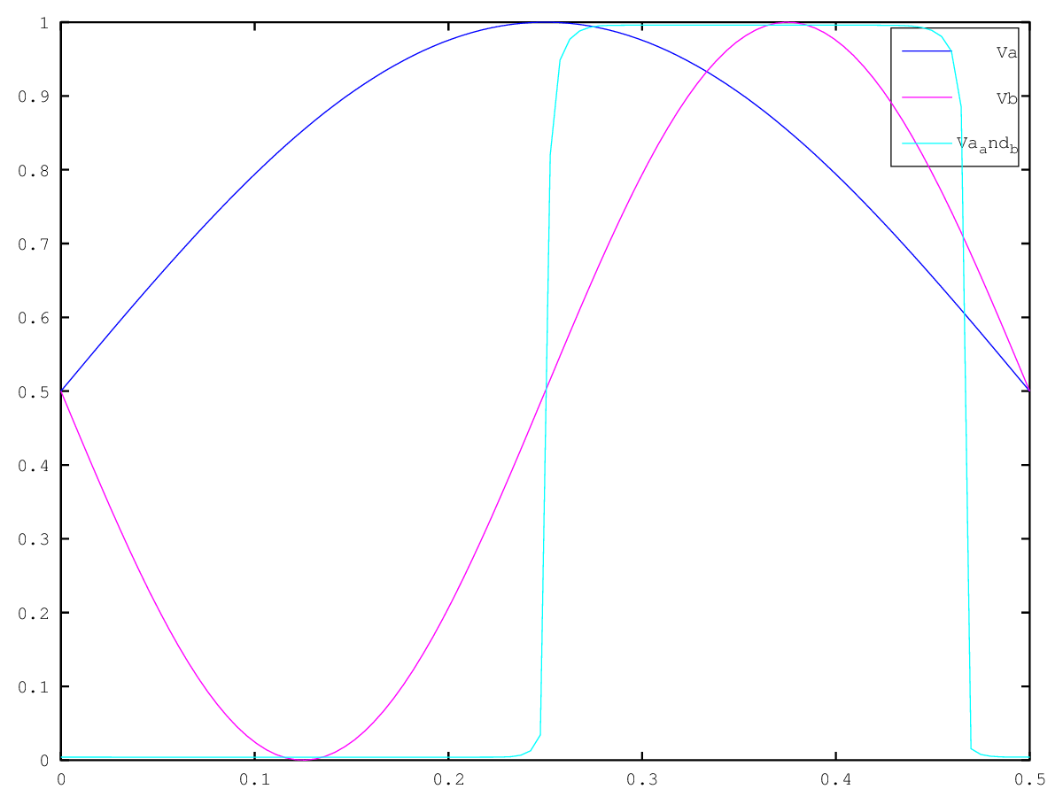 |
Package: ocs